| |
 |
  |
 |
|
» Hydra Nemesis Installation Instructions
Before starting the process of installing your Hydra Nemesis 2 plug and play system, disconnect the negative battery cable from the battery and push it aside so that it cannot make contact with the battery post during the installation.
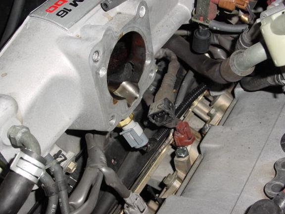
- 1. Open the trunk and using the tip of your key push in the middle buttons on the four fasteners holding the top of the trunk liner against the firewall separating the engine bay from the trunk. The fasteners should easily pull out. Peel back the trunk liner to expose the ECU on the left side of the car. Using a 10mm wrench, remove the three bolts holding the ECU to the firewall. Screw these back in a couple of turns when you remove the ECU because you will be using them later to bolt the Hydra Nemesis system to the firewall. To the left of the location where the ECU was bolted, there is a large hole covered by a grommet with a wiring harness passing through it. Just below and a little to the left of this large grommet is a smaller hole covered with a rubber cover just over 1/2" in diameter. Using a small flat-bladed screwdriver, gently pry off the cover and replace it with the grommet provided with the Nemesis.
- Using a flat-bladed screwdriver, carefully pull up the plastic step cover running along the lower part of the left door sill. You do not have to remove it completely, just loosen it so that the trim panel it touches on the rear side of the passenger cabin can be removed. Inside the passenger cabin, move the left side seat forward to permit you to access the rear carpet covering the firewall. If you are storing your T-tops here, remove them from the passenger cabin until the installation is complete.
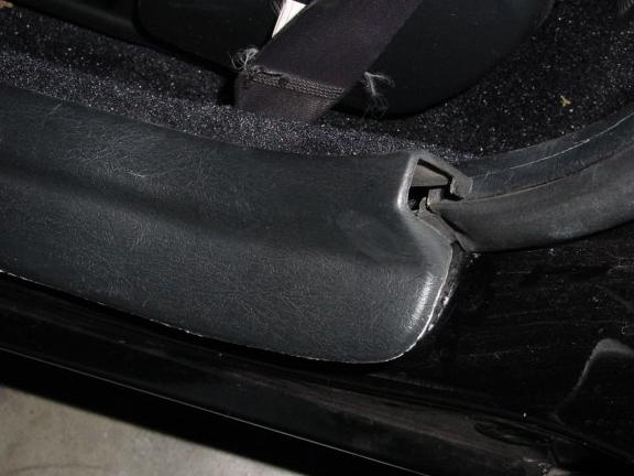
- Use a #2 Phillips screwdriver to unscrew the screw holding the plastic trim behind the engine lid opening lever and carefully pull it out.
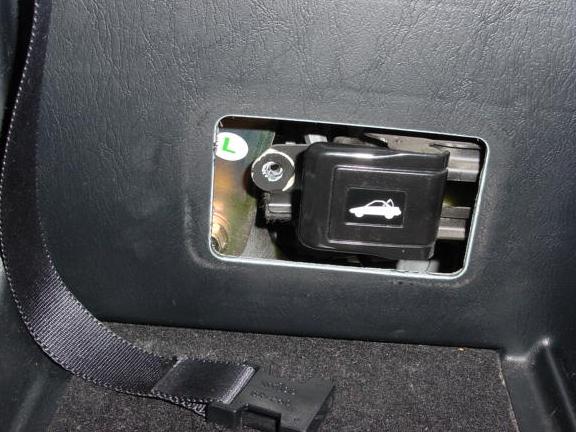
- Pull the lid covering the step behind the seat up and pry the plastic fasteners holding the lower side pillar cover to the lip of the step cavity. Unscrew the lid hinge and put the lid aside.
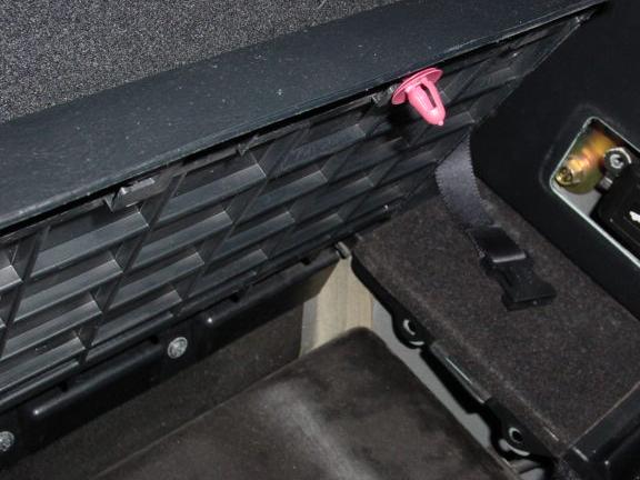
- Grab the edge of the lower side pillar cover and carefully pull it away from the chassis and set it aside.
-
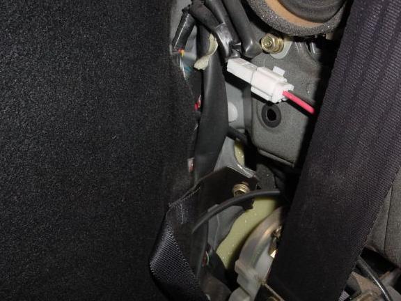
Carefully pull the lower right corner of the carpet back enough to expose the grommet covering the hole through which the main wiring harness passes to the engine bay. Unplug the two ends of the serial cable from each at the audio-style plugs found near one end of the serial cable. Put the very short end in the trunk and bring the long end with you into the passenger cabin. Using a Phillips screwdriver, carefully poke a small hole in the grommet and push the audio-style plug on the long end of the laptop cable through the hole to the engine bay. From the engine bay, carefully pull the serial cable out and feed it past the gas fuel filler pipe, under the air intake, the charcoal canister and the fuse box through the new grommet and into the trunk. If you find it hard to work your hand down to feed the cable into the hole, use a coat hanger or a length of wire fed in from the trunk side and electrical tape to secure the serial cable and carefully pull it through. You may also find it easier to temporarily remove the 1/2" grommet from the hole as you will be able to work it back on later when the serial cable, MAT sensor cable and vacuum line have been routed through the hole. Plug the short end of the serial cable back on. Snap the lower side pillar cover back in place arranging the laptop cable so that it easily reaches to the passenger seat and is not pinched by the plastic trim pieces. Push the fasteners back in place and screw the lid back on and snap it shut. Carefully work the trim piece back behind the engine lid opening latch and screw it into place.
-
If you are installing the Hydra Nemesis EMS on a gen3 engine with a gen3 engine harness, do not install the provided MAT sensor. You should skip past the next series of steps that describe the installation of the MAT sensor for the gen2 engine.
-
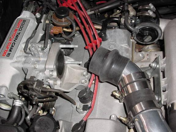
Loosen the hose clamps holding the intercooler to throttle inlet pipe and work the pipe off. Using a 12mm socket, take off the throttle body inlet and the two bolts holding the throttle body brace between the throttle body and the valve cover. Take off the two bolts holding the accelerator cable bracket and detach the cable from the throttle. Use a 10mm socket to remove the two bolts holding the valve cover side of the bracket and remove the bracket. Pull off one side of the little hose running between the valve cover and the throttle body.
-
Using a 12mm socket, remove the four bolts holding the throttle body to the intake manifold taking note of the fact that the two lower bolts are longer than the upper ones. Unplug the connector going to the throttle position sensor (four pins) and pull the throttle away from the intake manifold so that you can access and pull off the connector to the idle speed valve (three pins) under the throttle body. Do not detach the hoses connected to the idle speed control valve but gently move the throttle body out of the way so that you can access the cold start injector underneath the throttle body attachment point on the intake manifold.
-
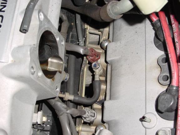
Using a small flat-bladed screwdriver, pry the retaining clip off the cold start injector connector. It is not easy to do, but there is a small notch on the very top of the edge facing towards the front of the car that you can use to pry the clip out. When the clip is out, the connector will slide out easily. Use a little electrical tape to wrap the cold start connector so that it does not make contact with anything and short the electrical system. Use a 10mm closed-end wrench to pull off the two bolts holding the cold start injector to the intake manifold. Pull off the cold start injector and remove and clean the gasket behind it. If it is broken and not reusable, obtain a new gasket from your Toyota dealer before proceeding to prevent boost leaks. Using a 10mm wrench, unbolt the union bolt holding the cold start fuel line to the fuel rail. Prepare a small container or rag to catch the fuel that will run out of the cold start injector fuel line when you pull it from the fuel rail. Save and clean off the seal washer on the union bolt.
-
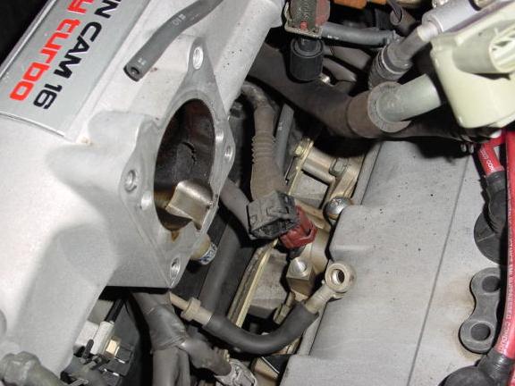
Use the original seal washer and the 8x1mm bolt supplied with the Hydra Nemesis 2 to plug up the fuel rail. Do not torque the plug over 10 ft/lbs. Locate the manifold temperature sensor and the mounting plate provided with the Hydra Nemesis 2 and screw the sensor snuggly into the plate.
-
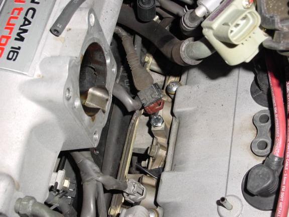
Using the bolts and the gasket originally on the cold start injector, bolt the mounting plate onto the intake manifold with the measuring tip of the sensor pointing up into the manifold. You should see the tip poking out of the hole in the bottom of the manifold when the plate is firmly reattached. Do not torque the bolts over 10 ft/lbs. Locate the temperature sensor cable provided with the Hydra Nemesis 2, snap the connector on the cable onto the manifold temperature sensor and snake it under the fuse box and through the hole with the new grommet into the trunk. Wrap electrical tape over the cold start injector connector to prevent it from shorting against the throttle body or valve cover and potentially blowing a fuse.
-
Line up the throttle body back on the intake manifold first reconnecting the idle speed valve connector (three pins) and the throttle speed sensor connector (four pins) and placing the gasket that goes between the throttle body and the intake manifold back in place. Put the four bolts that hold the throttle body back in place (the longer ones go an the bottom) and torque them to 13 ft/lbs. Push the little hose that goes between the throttle body and the valve cover back into place. Put the bracket that secures the throttle body against the top of the valve cover back on and torque the 12mm bolts to 13 ft/lbs. and the 10mm bolts to 8 ft/lbs. Put the throttle body inlet back on remembering the gasket between the throttle body and the inlet and torque the four bolts to 13 ft/lbs. Reattach the throttle cable and bolt the throttle cable bracket onto the throttle body. Torque the two bolts holding the throttle cable bracket to 13 ft/lbs. Work the intercooler to throttle body inlet pipe back in place and tighten the clamps properly so that they do not pop off the next time you boost.
-
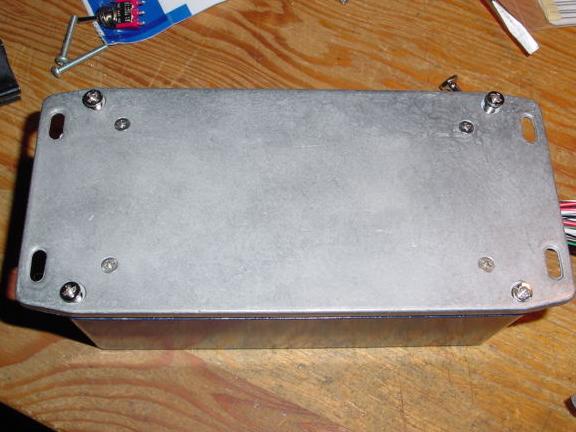
The plug and play box comes programmed for the type of engine that you indicated you had when you ordered the unit. If you suspect that the box is not properly configured, open the box by unscrewing the four larger screws on the base of the board.
-
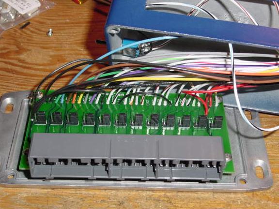
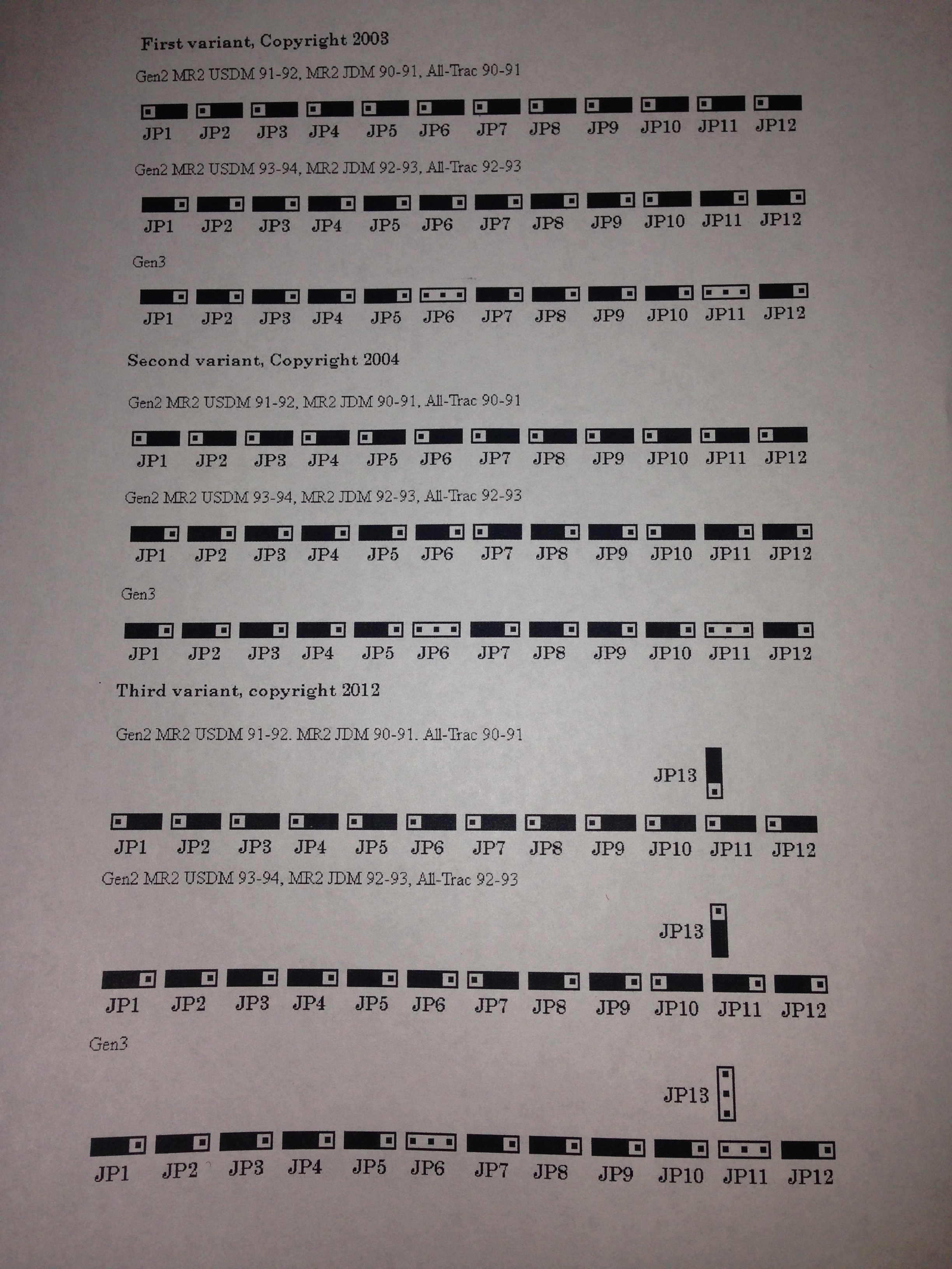
Carefully pull the top of the plug and play box forwards to clear the main connector and then upwards to pull it away from the base. Grab the wire bundle coming out of the hole on the side of the plug and play box and gently push inward to give the wires extra slack to allow the top to be moved upward enough to expose the entire circuit board inside. The configuration jumpers are now exposed and can be easily set by pulling each jumper off and reinserting it in the position shown here.
-
Inside the engine bay, locate a small black box sensor attached to the same bracket holding the connector labeled "Diagnosis." There should be a label on this sensor reading "Turbo Pressure Sensor." There is a short 4mm inner diameter hose connecting this small box to a vacuum port on the intake manifold. Remove this hose and run the provided 4mm vacuum hose from the manifold port where this was connected to the port on the Hydra Nemesis EMS -- DO NOT TEE INTO THIS LINE. Feed the hose around the back of the intake manifold and under the fuse box and feed it through the hole with the new grommet into the trunk. You may need to temporarily slide the 1/2" grommet off the sheet metal to give the hole a little more room to squeeze the hose through with the serial cable and MAT cable already there. If you want to retain the original function of the turbo pressure sensor for the dash gauge, you can re-tee this into a different line coming from the intake manifold (like the fuel pressure regulator).
-
Insure that the three connectors on the plug and play box are securely connected to the corresponding connectors on the Hydra Nemesis 2. Note that the two smaller connectors are identical except for their color and that they must be plugged into the matching color connector on the Hydra Nemesis 2 unit. Lay the Hydra Nemesis 2 face down on the bottom of the trunk and connect the three stock connectors that used to plug into the stock ECU into the main connector on the end of the plug and play box. For the Hydra Nemesis 2.1 and 2.5 systens, partly screw in the two bolts on the left side of the firewall that originally held the stock ECU and slide the two tabs of the bracket underneath the heads and washers of these bolts. Insert the last bolt that held the stock ECU into the remaining bolt hole and tighten all three bolts with an open-end 10mm wrench. For the Hydra Nemesis 2.6 system, pull the unit off the bracket which is secured with Velcro and you will be eble to easily access the bolts and tighten then with a 10mm socket.
-
Push the 4mm hose from the intake manifold into the vacuum port on the Hydra Nemesis 2. You can carefully trim off any excess length from this hose before doing so to keep it from kinking or tangling. Connect the manifold temperature sensor cable to the connector labeled 'MAT' on the plug and play board. Connect the serial cable to the Hydra Nemesis 2 and secure it with the two small screws on the serial connector. Position the switch on the left side of the plug and play box with the labels 'Test' and 'Race' to its center position. On newer plug and play boxes there is no 'Test' label because this function is selected by putting a jumper across T and E1 in the diagnosis connector just as you would if you had a stock ECU. In this case, the switch just has two positions and you should set it to the one pointing away from the 'Race' label.
-
Double check all connections to insure that they are tight and all screws and bolts are securely tightened. Reconnect the battery. Using a bent paper clip, connect the +B and Fp terminals in the 'Diagnosis' box and turn the ignition key to 'ON' without attempting to start the engine. The fuel pump will run and the fuel system will pressurize. Use your nose and a flashlight to insure that the cold start fuel feed plug inserted in the fuel rail is not leaking. If you smell or see any gasoline, quickly turn off the ignition and fix the cause of the leak. Do not continue until the leak is fixed. Turn the ignition key to 'OFF' and pull out the paper clip.
-
Insert the software CD provided with the Hydra Nemesis 2 in your laptop's CD-ROM drive. At this time you may want to read the User's Manual provided as a PDF file on the CD and familiarize yourself with the basic features and navigation of the laptop software. Then, run the installer (the file named 'Setup.exe') to install the Nemesis program on your laptop. You can also download the latest installer Nemesis 2.17v1. Connect the serial cable in the passenger cabin to the laptop computer. Note that it is strongly recommended that you either use a laptop computer with a built-in serial connector or that you purchase a PCMCIA serial interface to connect to the Hydra Nemesis 2.1 or 2.5 systems. The Hydra Nemesis 2.6 system comes with a USB to Serial converter that has been tested and known to work with the system. Other USB to serial interfaces may not work or require that you spend a lot of time playing with the advanced setup features of the interface to find a combination of settings that sometimes work. Use these interfaces at your own peril.
VERY IMPORTANT: DO NOT use the version 2.1 or 2.5 download button or the version 2.6 'File->save to ECU' menu item on the laptop software to send a new set of maps to the Hydra Nemesis 2 unit until you have managed to upload the maps that where shipped with the Hydra Nemesis 2 unit and saved them on your laptop. Most of the cases where the Hydra Nemesis 2 unit fails to start the motor are a result of doing a download with an improperly configured serial interface that is unable to do a successful upload much less have a chance of doing anything except downloading complete and total junk to the Hydra Nemesis 2 unit that may require you to send back your unit to us to get it fixed.
-
There are several unconnected wires attached to the plug and play box with blade connectors. Do not remove the blade cap to any of these wires unless you are going to connect the connector to another wire or solenoid as some of these wires could cause problems if they were to short against each other or against the chassis. The solid red wire is switched power and supplies 12 volts when the ignition key is 'ON.' Do not use this wire to power any accessory as it is connected to the Hydra Nemesis 2 power supply and is only intended for use in powering relays to switch on larger amounts of current such as to power water injection pumps or cooling fans. The white wire with a yellow stripe or red wire with a yellow stripe is unswitched power and is used by the optional turbo timer kit.
-
Start the laptop software and turn the ignition key to 'ON.' The check engine light on the dashboard should light up. If it does not, verify that the Hydra Nemesis 2 unit is getting power by checking the EFI fuse in the engine bay fuse box. Use the 'Upload' button in version 2.1 and 2.5 or the 'File->Load from ECU' menu item in version 2.6 to load the base program stored in the Hydra Nemesis 2 unit to the laptop. Use the 'Maps' button in version 2.1 and 2.5 to enter the map adjustment portion of the program. On the front panel, locate the 'BATT,' 'AIR' and 'COOL' values, which indicate the battery voltage, intake air temperature and coolant temperature, respectively. Verify that these values are reasonable. In particular battery voltage should be near 12 volts for a healthy battery and the air and coolant temperatures should be close to the ambient temperature (unless the engine is still warm from having been operated before you began the installation). Use the 'Select->Settings' menu item in version 2.1 and 2.5 and the Map Group->Settings 1 menu item in version 2.6 to bring up the settings panel. Click on the 'THROTTLE' button to select the throttle settings panel in version 2.1 and 2.5 or select the Tools->TPS/PPS calibrate menu item in version 2.6. Click on the 'calibrate zero' to set the closed throttle position. Press the gas pedal down all the way and keep it there. Click on the 'calibrate WOT' button to set the open throttle position. Close the settings panel by pressing the 'Ok' button. Locate the 'TSP' value on the front panel and verify that it goes from 0 to 100 as you move the throttle. Select 'Maps->Save' in version 2.1 and 2.5 and 'File->Save to file' in version 2.6 to save the base map to a file.
-
If you purchased the wideband feature, follow the directions in the wideband installation section at this time.
-
The Hydra Nemesis 2 unit is capable of operating low impedance fuel injectors directly without a fuel injector resistor pack. When using large injectors, it is particularly important to actually eliminate the fuel injector resistor pack. Keep in mind that if you eliminate the fuel injector resistor pack you must never try to run the car with a stock ECU unless you replace the resistor pack as doing so will damage the stock ECU and the injectors. You can eliminate the resistor pack by unplugging the pack which is bolted to the rear firewall from the engine harness. This pack is the one that has five wires going to it. Using a pair of diagonal cutters, cut off the plug from the resistor pack leaving about two inches of wire connected to the connector. Strip off about 1/2" of insulation off the end of each of the five wires connected to the connector and twist all five wires together to make good contact. Use a soldering iron and solder to solder these five wires together. Wrap the exposed solder connection with electrical tape or heat some shrink tubing over it to cover it completely. Plug the connector back into the engine harness. You have now electrically eliminated the fuel injector resistor pack.
-
At this point, you should load the appropriate injector response curve into your Nemesis map. Turn the ignition to 'OFF' and load the map file that you saved from the Nemesis using the 'File->Open' menu item. Click the 'Maps' button and then 'OK' when the laptop program tells you that the ECU is not connected. Go to 'Tools->Load injector response.' If you are running the Hydra Nemesis 2 with the fuel injector pack still in the car using either stock or Supra injectors, select '8 OHM INJECTOR' and click the 'Load' button. If you are running without the fuel injector pack, use an ohmmeter to measure the resistance in ohms across the two terminals of any one of your fuel injectors then select the value from the panel that most closely matches the resistance you measured and click the 'Load' button. Once you have done so, select 'Maps->Exit' to go back to the laptop program entry screen. Use 'File->Save' to save the maps with the proper injector response curve. Turn the ignition key to 'ON' to power up the Hydra Nemesis 2 unit and then click the 'Download to ecu' button and 'Download' to load the new injector response curve into the unit. Switch the ignition key to 'OFF' when the download completes. Note that if you reload the map and go into the load injector response panel again, that it will always have the 16 ohm option selected. This is normal regardless of which option you loaded last.
-
Turn the ignition key to 'ON' and attempt to start the engine. If it starts and settles into an idle, you have a big smile on your face and you can go on to the next paragraph. If it starts and stalls, try again a couple of times. If it idles after one or two tries, you most likely just need to adjust the cold start parameters a little bit. If it continues to stall, try giving it a little gas after it starts and see if you can keep it going. If you can, then most likely your idle map is a little too lean for your engine or your idle screw needs adjustment to give the engine enough air to keep it running. If it doesn't start or won't keep running even with some gas, you need to go to the troubleshooting primer.
-
After you get the engine to start and run, let it warm up and bring it to a stable idle between 800-1200 RPMs. At this point, verify your ignition timing before you proceed with tuning the Hydra Nemesis 2. The process of checking the ignition timing is very similar to what you do to check ignition timing with the stock ECU except that instead of putting a jumper in the 'Diagnosis' connector, you need to flip the switch on the left side of the plug and play enclosure upwards to the 'Test' position to get the base map to select a timing of 10 degrees BTDC. On newer plug and play boxes, there is no 'Test' label on the switch and if this is the case, then use a jumper between the 'TE1' and the 'E1' pins in the 'Diagnosis' connector to check the base timing just as you would in the with the stock ECU in place. With the engine running and warm, the right side trim plate removed and a timing light connected, flip the switch to 'Test' or put the jumper in place and verify on the main software panel that the 'ADV' value is 10 (hit the 'Mode' button to switch to digital mode if the 'ADV' box shows a bar instead of a number). If 'ADV' is not 10, then you have either modified the base map timing maps so that they no longer gives 10 degrees of timing when you switch to test mode or maybe the engine has not yet reached an operating temperature between 80-100 degrees Celsius. Whatever the 'ADV' number is (assuming that it is stable), that is the amount of advance that you should read when you point the timing light at the crankshaft pulley. If it is off, loosen the distributor and turn it clockwise to advance and counterclockwise to retard the timing mark until the reading on the pulley matches the value in the 'ADV' box. Once you have a match between the timing light reading and the laptop screen ADV number, tighten down the distributor and move the switch on the plug and play box back to the center position or pull the jumper out.
If you have the boost controller feature, follow the directions in the boost control installation section at this time to install the boost controller and program it.
If you have an aftermarket MSD ignition system or purchased the direct fire ignition option, follow the directions in the ignition installation section at this time to connect the ignition system.
If you have the launch control cable, follow the directions in the launch control section at this time to set up your launch control system.
If you have the turbo timer option, follow the directions in the turbo timer section at this time to set up your turbo timer.
At this point, you are ready to tune your car for best drivability and power. You can learn more about this in the Nemesis tuning primer.
When you are finished tuning the car, you should remove the black wire going to the B10 pin on the small blue connector on the Hydra Nemesis 2 unit. Only older version 2.1 units had this feature. This will prevent the Hydra Nemesis 2 unit from being programmed on the fly and enable the backup spark map when the knock detection system parameters instruct the unit to fall back to the backup spark map. Turn the ignition key to 'OFF.' Carefully unplug the three connectors from the right side of the Hydra Nemesis 2 unit. On the small blue connector, look at the back where the wires come out and locate the markings on the corners that distinguish row A from B and the B1 pin from the B12 pin. The B10 pin is the third pin from the pin labeled B12 which is a solid black wire. Use a small flat-baded screwdriver to pull off the plastic retaining clip on that row of pins. Then, use a straightened out paper clip or a small jeweler's screwdriver on the large hole in the front of the connector for B10 to carefully push back the locking tab for the B10 wire while tugging gently on the black wire to release it. Use a little bit of electrical tape to prevent this pin from contacting anything. |
| |
|
 |
|
|