1 container of anti-seize rated at 1800 degrees or higher.
NOTE1: In the following instructions, when a bolt is referred to as a "14mm" for example, this indicates the size of the wrench required to remove it, not the shank size as is standard.
Click any image for a larger size.
NOTE2: These instructions assume that you have already upgraded to an aftermarket downpipe on a CT26 or CT20b. If that is not the case, then refer to the first half of the KO Racing downpipe installation instructions for removal of the stock Primary cat and turbine outlet elbow.
Ensure that the rear of the car is elevated and properly supported with jack stands or ramps to allow access to the primary catalytic converter or downpipe, but not so high that you can't reach into the turbo area of the engine bay from the top (about 11" of clearance from the cross member to the ground), and that the car has properly cooled down ~45 minutes.
Step 1:
The first thing you need to do is to spray all visible fasteners with PB blaster or equivalent bolt loosener and allow it to soak (like 1 day if you have time, or 30 minutes if not) on the Turbine bolts, and any fasteners holding the downpipe in place. Remove the strut tower brace if you have one that goes over the turbo location (like stock or a TRD). There are 2 14mm nuts on the strut towers, and 2 14mm bolts on the firewall end of the brace -- these can be pretty tight.
Step 2:
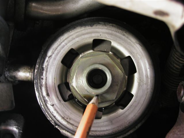
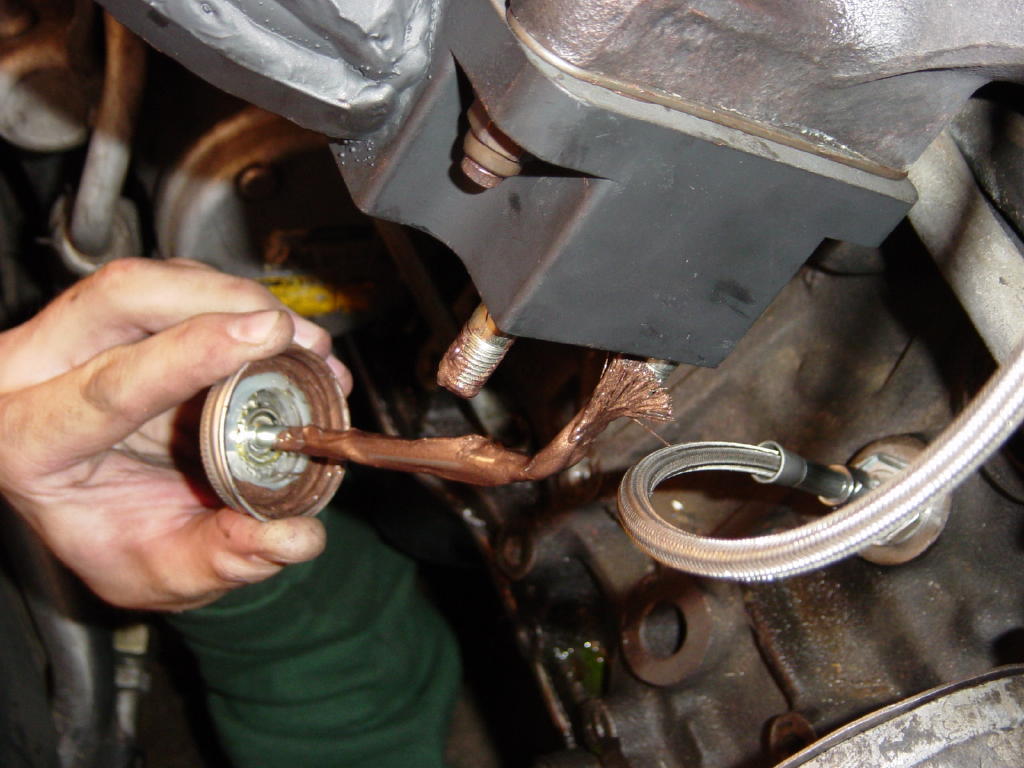
Remove the oil filter being careful to not spill oil out of it (as much as you can since it's mounted upside down).
Step 3:
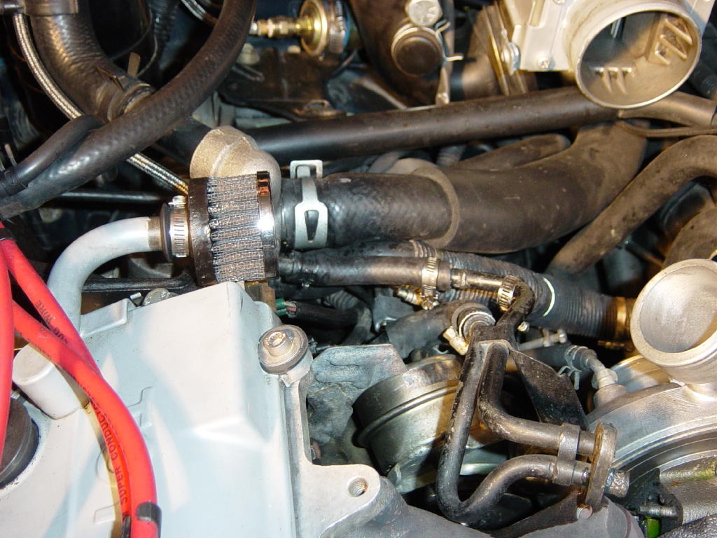
Remove the turbo to intercooler cast aluminum pipe and blow off valve as a unit by loosening the 10mm fasteners on the hose clamps and removing the pinch clamp from the boost/vacuum line that runs from the area near the distributor cap to the blow off valve.
Step 4:

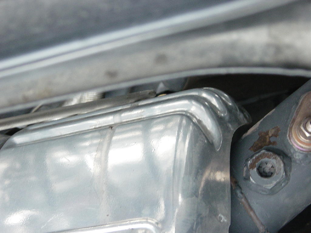
Remove the 3 12mm bolts holding the turbocharger heat shield in place (the one with the "Caution: HOT" written on it) and remove the heat shield. One is down on the side of the heat shield toward the firewall out of plain view -- but you should be able to get a combination wrench on it.
Step 5:
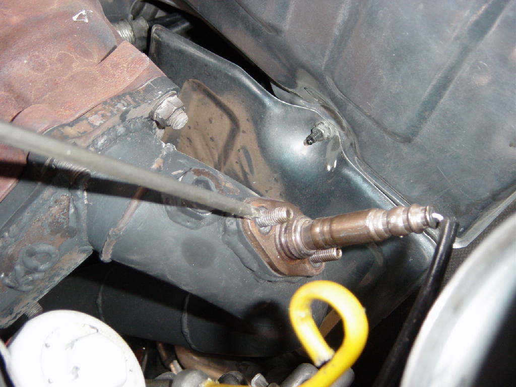
Remove the 2 12mm nuts holding the oxygen sensor in place and remove the oxygen sensor being very careful to not bang the oxygen sensor into anything as it is easily damaged. Retain the stock oxygen sensor gasket for reuse, or if it's damaged, you can order a new one from Toyota or your local autoparts store. Now head under the car.
Step 6:
Remove the small plastic underbody pan that is directly below the catalytic converter (there are 6 10mm head fasteners -- note that one has coarse threads and threads into plastic and not metal).
Step 7:

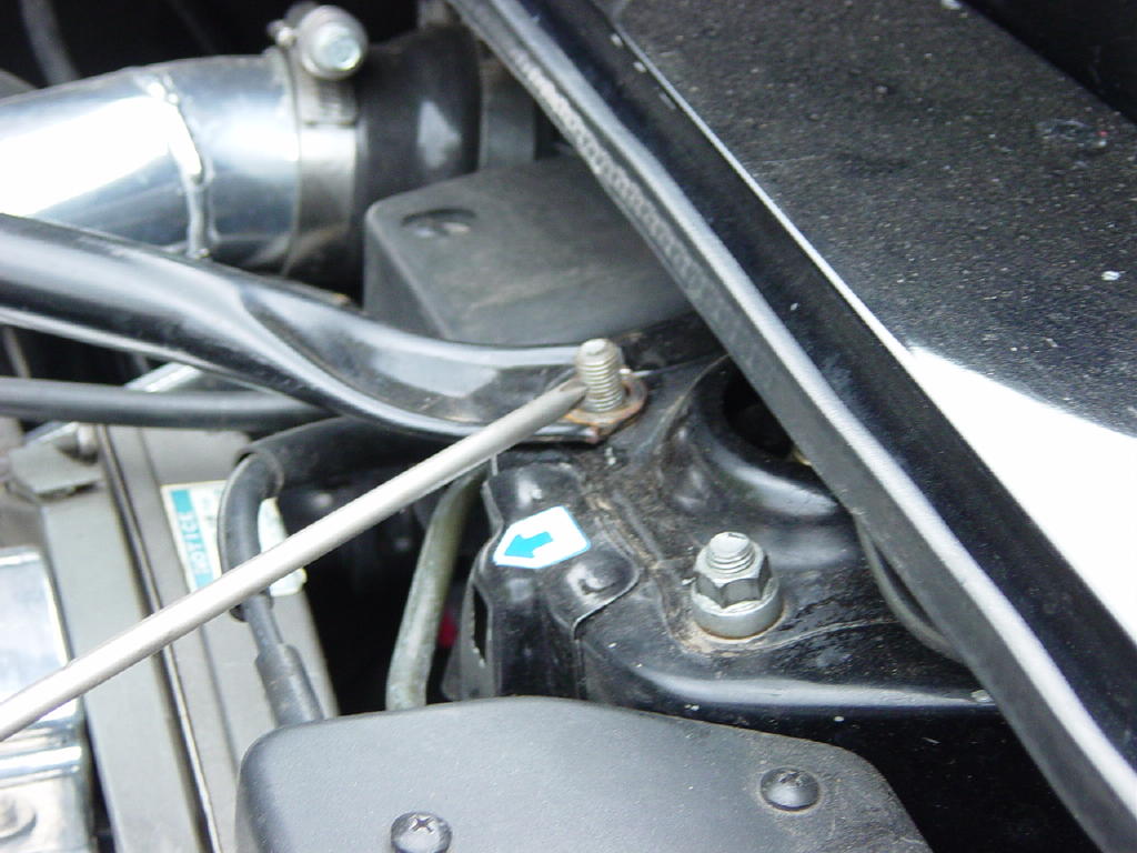
Remove the 3 14mm (9/16" for KO Racing downpipe) bolts holding the b-pipe to the end of the downpipe (remove the b-pipe completely if possible for extra under car clearance). Remove the downpipe support bracket (that is if you have one).
Step 8:
Remove the 2 12mm nuts holding the stock oil feed/return lines to the bottom of the Toyota CT26 or 20b turbos.
Step 9:
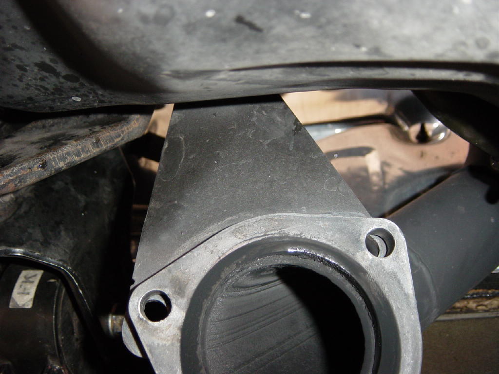
Remove the 6 14mm head nuts that fasten the downpipe to the turbine outlet. These are likely to be seized up (good ol' PB Blaster).
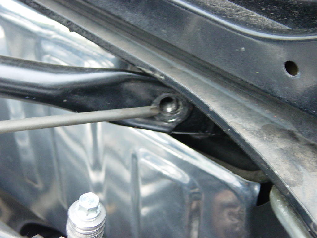
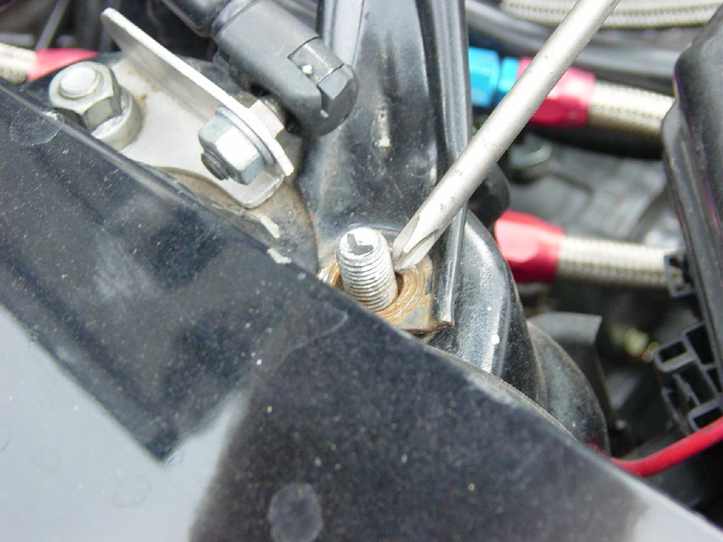
Step 10: (NOTE: This step is not always necessary.)
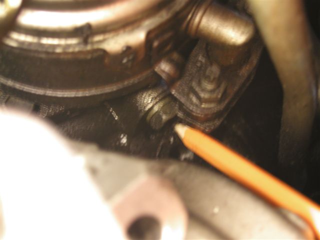
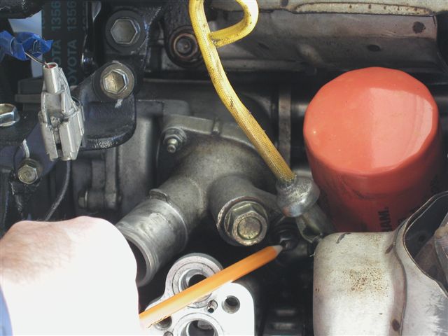
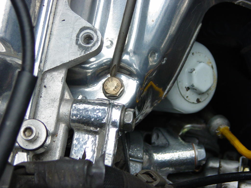
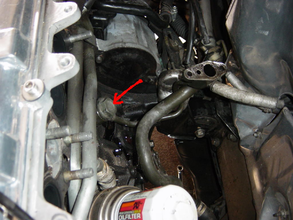
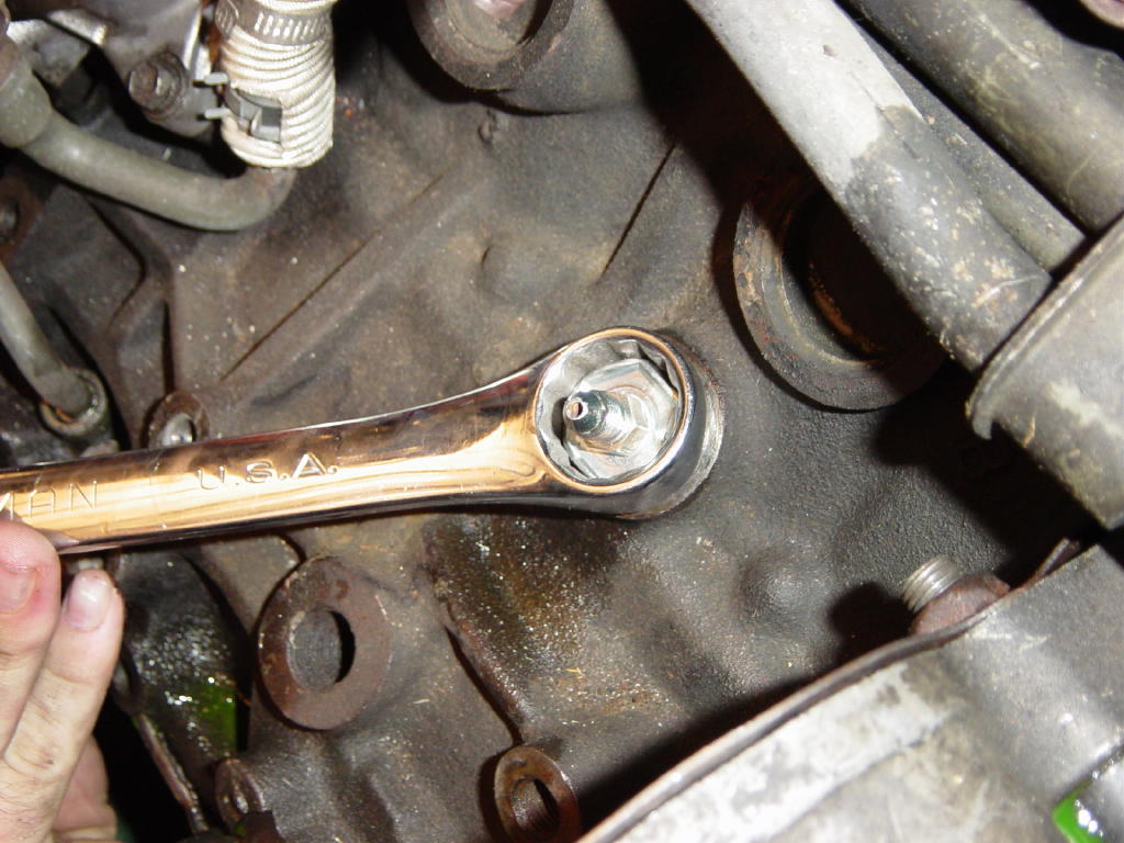
Remove the 12mm bolt down on the side of the oil cooler (where the oil filter mounts). Once the bolt is out, go back up top.
Remove the 30mm stud that holds the oil cooler in place (this is where the oil filter screws on). Be careful to not allow any foreign particles to enter into the oil system through this location (keep it covered with a clean rag).
Step 11:
Remove the downpipe from the car.
Step 12:
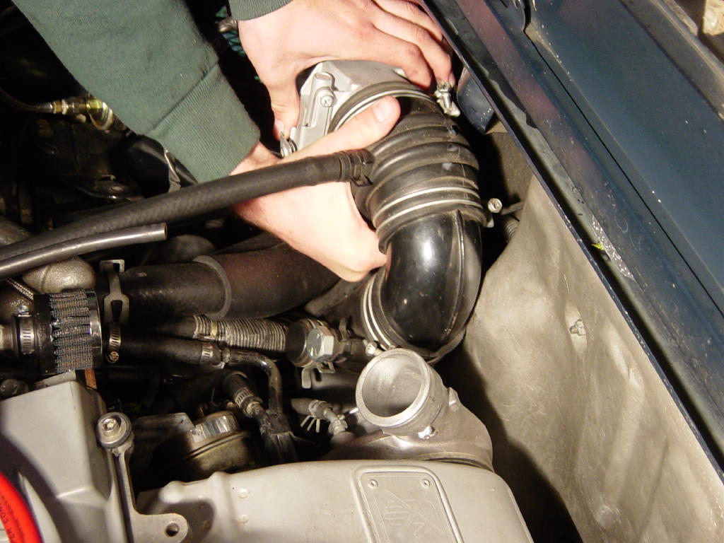
Remove the stock air flow meter and air intake piping from the inlet of the turbo. Be careful to not damage the AFM (Air Flow Meter) -- the connector uses a small metal wire clip to retain it on the AFM -- DO NOT REMOVE THE TWO PHILLIPS SCREWS THAT MAY SEEM TO BE HOLDING THE CONNECTOR IN PLACE, THIS WILL DAMAGE YOUR AFM.
Step 13:
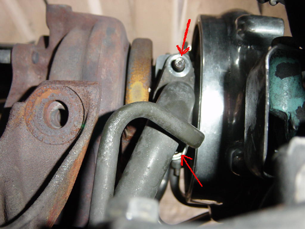
Remove the 2 12mm bolts holding the water lines to the compressor housing on the stock turbo.
Step 14:
Remove the 2 10mm nuts holding the water lines into the side of the CHRA (Center Housing and Rotating Assembly) of the turbo -- AKA the middle part -- and pull the water lines out. There will be a small amount of water loss upon removal of these lines, so be sure to have something to catch it on the ground, or at the very least, give some warning to your helper who's working under there while you do this (but it may be funnier to not warn them!).
Step 15:
Pinch the clamps and remove the rubber hoses that connect to the stock hard water lines. Remove the upper of the 2 rubber hoses from the car (this hose goes to the stock water neck).
Step 16:
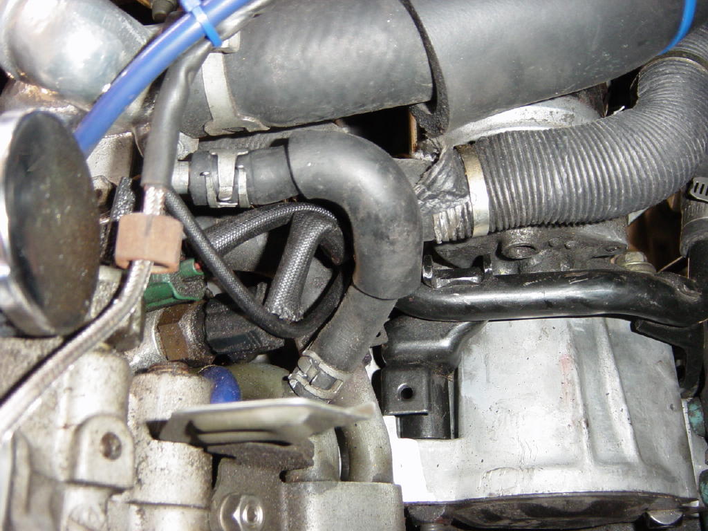
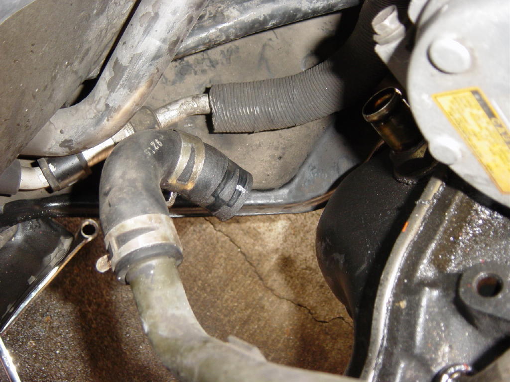
Pinch the clamp holding the remaining turbo water hose on the car (to a pipe running along the engine block) and twist the hose to make it go onto where the other turbo rubber hose came out of the water neck. Unpinch the clamps and your water lines are now re-routed to no longer go to the turbo. It may be necessary to replace this hose if yours is old and cracking -- twisting an old dried out hose can cause it to crack and leak. If you want to replace the hose, either order the replacement part from Toyota, or use a short length of 3/8"ID straight hose from the local auto parts store.
NOTE: If you have a GT series or optionally water cooled t3/t4, remove this hose from the engine completely. You will need to run your water lines provided with your turbo kit to where the two hoses on the stock turbo ran. One on the metal water lines running to the engine, and one to the port on the water neck. It does not matter which line goes to which connection.
Step 17:
Remove the vacuum/boost lines going to the wastegate actuator from whatever boost control device you are using.
There are two methods of removing the stock turbo -- one is to remove the manifold and turbo together, the other is to leave the manifold in the car and remove the turbo from it. The latter method is outlined here. Removal and installation of the manifold can lead to stripping the manifold studs out of the cylinder head, and making the whole project take twice as long.
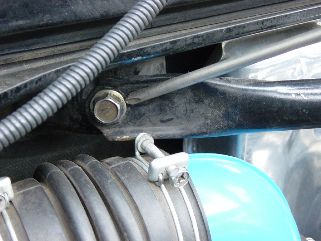
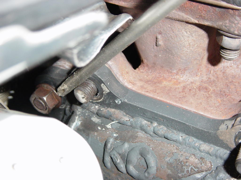
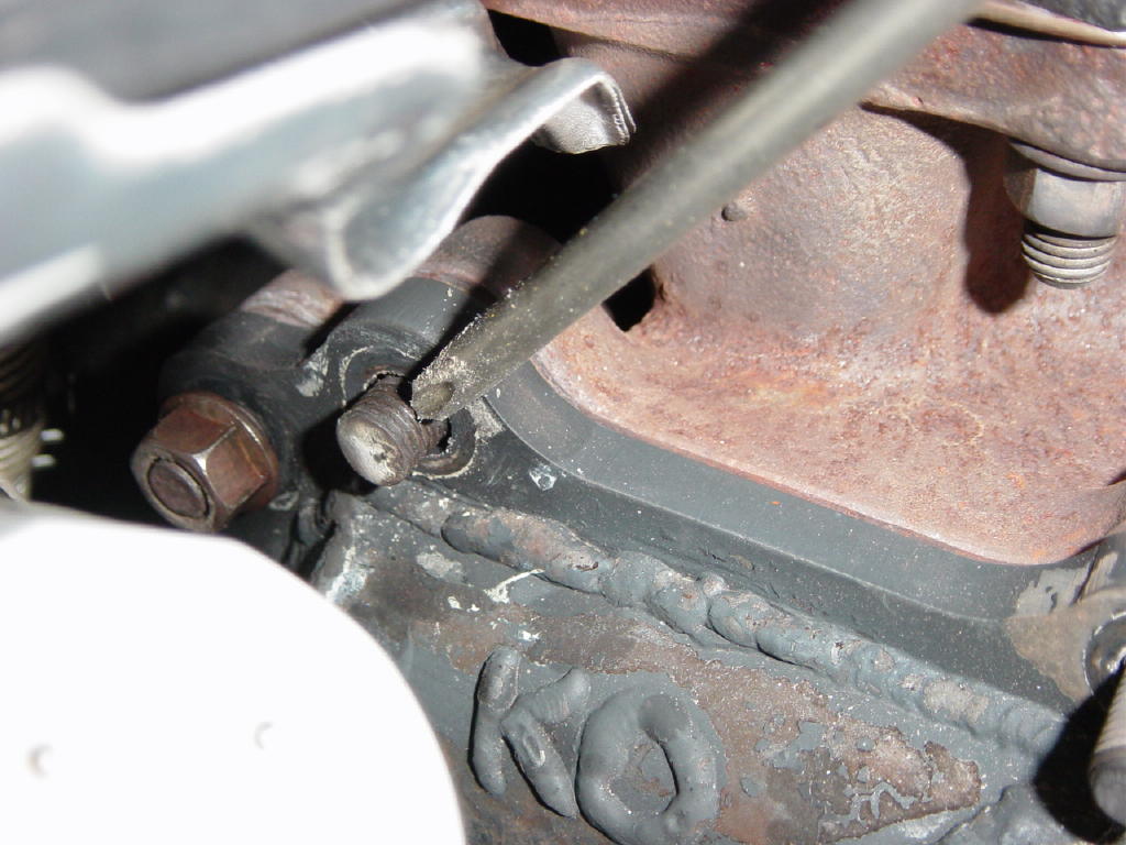
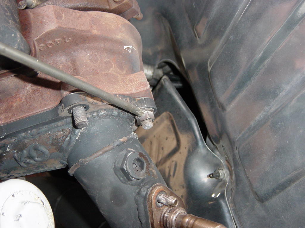
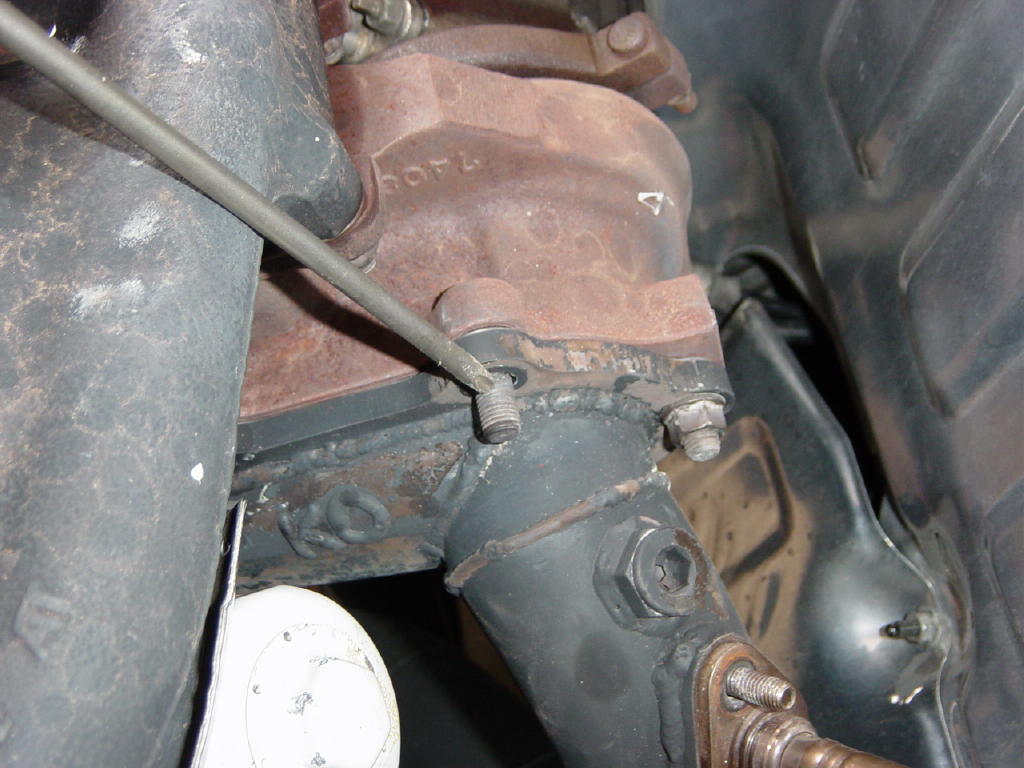
Step 18:
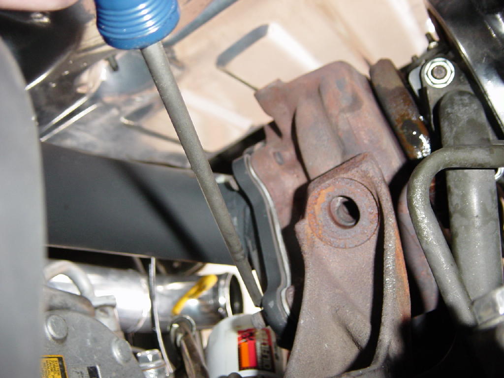
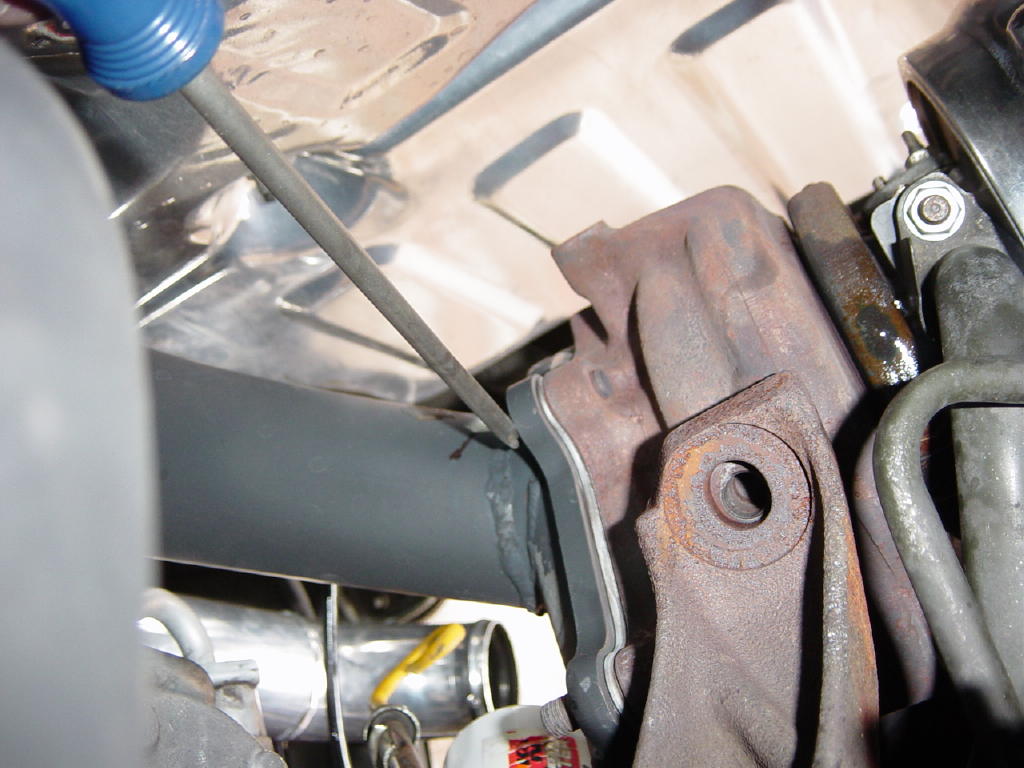
Remove the 2 12 or 14mm (I've seen it installed with either) bolts holding the stock turbo mounting stay to the side of the engine block, and remove the large nut holding the turbo stay to the bottom of the turbo. Remove the stay from the car.
Step 19:
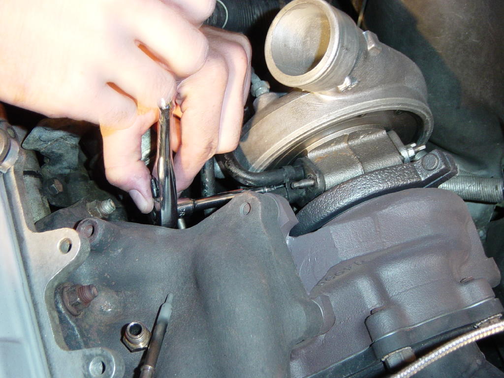
Remove the large hose at the end of the oil return line going to the stock oil pan fitting. Remove the 22mm nut holding the oil feed line into the engine block (this can be done with a 1/2" drive socket and a 3" extension on a breaker bar from the top). Remove the oil feed/return lines.
Step 20:
Loosen the 2 14mm nuts holding the turbo to the exhaust manifold that are accessible from the top of the car. Then go under the car and remove the 2 rear (near the enging block) 14mm nuts holding the turbo to the exhaust manifold. Go back up top and remove the 2 14mm nuts and the turbo.
Step 21:

Once the turbo is out of the car, remove the clutch slave cylinder heat shield by removing the 2 12mm bolts holding it in place. The clutch slave lines will be very tight but should clear the turbo compressor housing once the turbo is installed. For extra clearance, loosen the bolt holding the clutch slave cylinder lines down and use a dead blow hammer or rubber mallet to bend the lines over toward the driver's side of the car a bit (.25" max). Over several years of testing, we have proven that the proximity of these lines to the turbo has no adverse affect on the operation of the clutch slave cylinder.
Step 22:
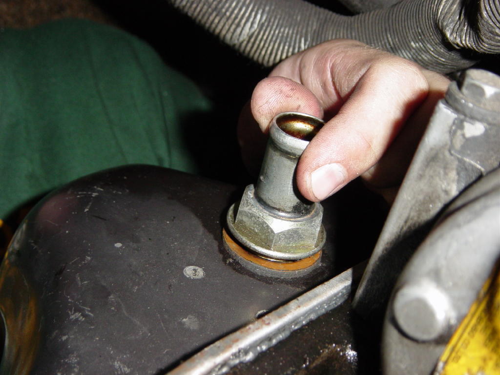
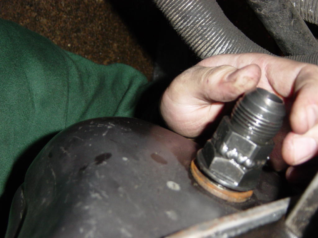
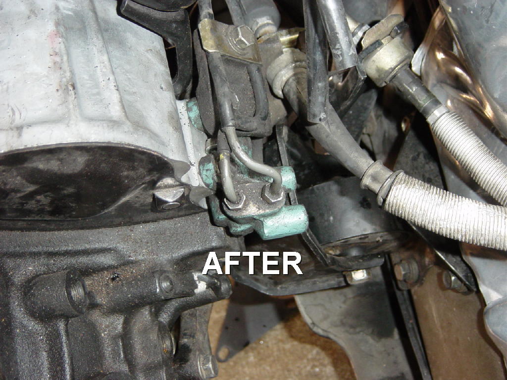
Remove the stock oil return fitting from the oil pan (it unscrews), and install the fitting supplied in the Street Brawler turbo kit. Be sure to put a very light coat of RTV silicone on both sides of the brown ring gasket supplied with the Street Brawler turbo kit before installing the -12AN oil pan adapter. Tighten this fitting in to the oil pan.
Step 23:
Install the oil feed adapter into the engine block with the aluminum crush washer/gasket supplied with the turbo kit. Be sure to tighten this adapter to approximately 30-40 ftlbs to ensure a leak free seal.
Step 24:
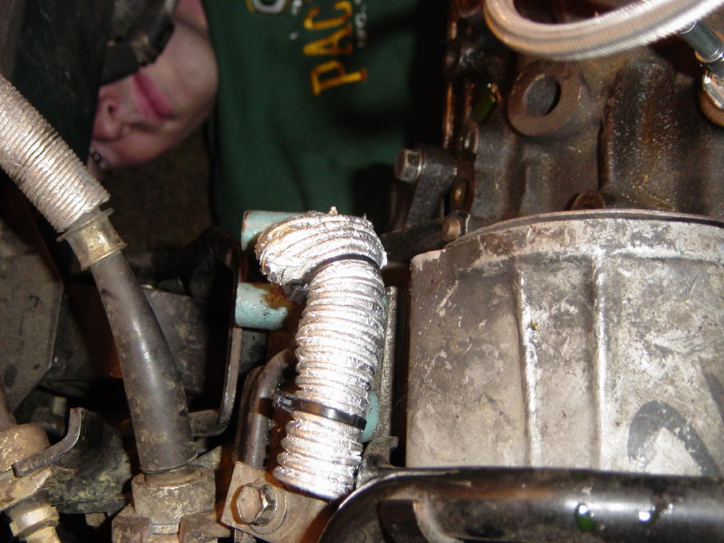
Put the heat insulating sleeve material over the clutch slave lines and secure it with zip ties.
Step 25:
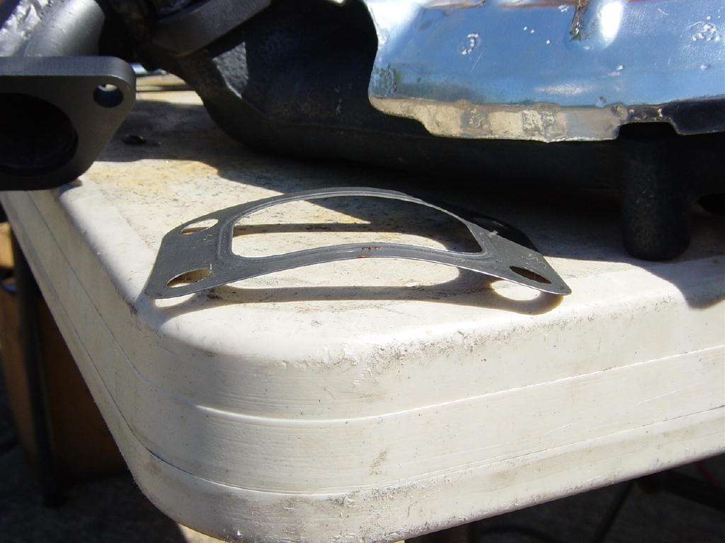
Inspect the gasket that came off of the stock manifold where the stock turbo mounted. If it is in need of replacement due to excessive cracking or leaking, order a new one from Toyota. Ensure the threads on the studs sticking out of the exhaust manifold are clean and their nuts spin down freely. Install the gasket onto the manifold.
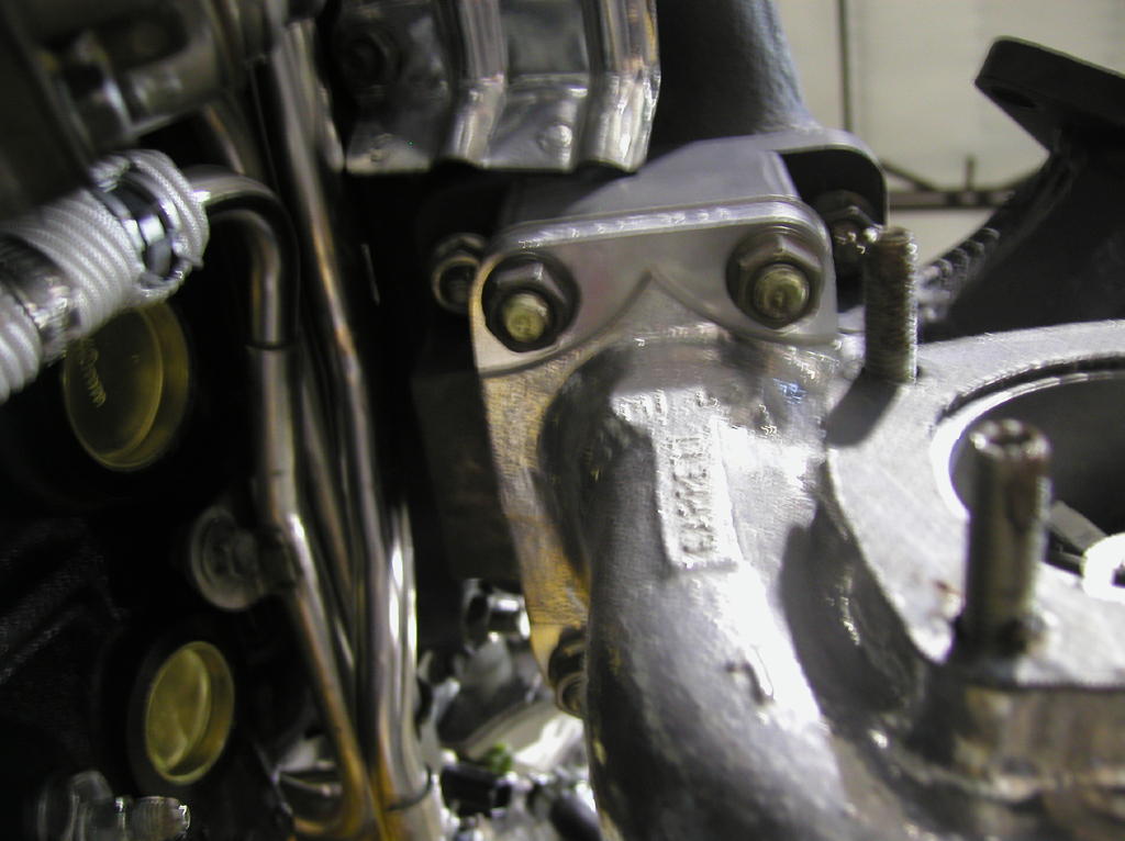
Step 26:
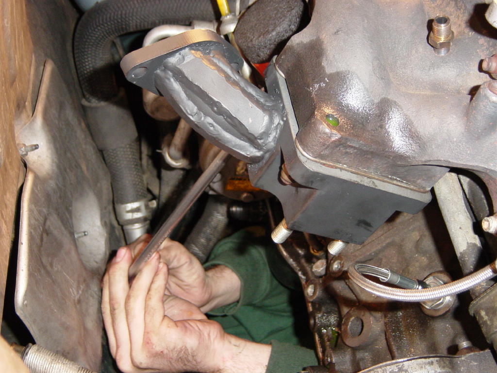
Install the Street Brawler turbo adapter onto the manifold being sure to locate the wastegate mounting flange away from the engine block. Start all 4 14mm nuts before tightening any of them (use anti-seize). Once they are all started, torque them to approximately 50 ftlbs (pretty darn tight). Also install the oil pressure feed line (-3AN) onto the block oil adapter and tuck the other end of the line out of the way.
Step 27:
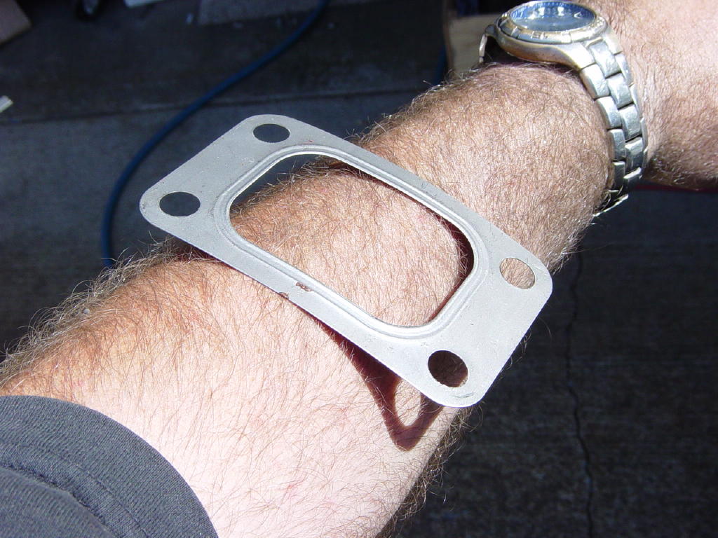
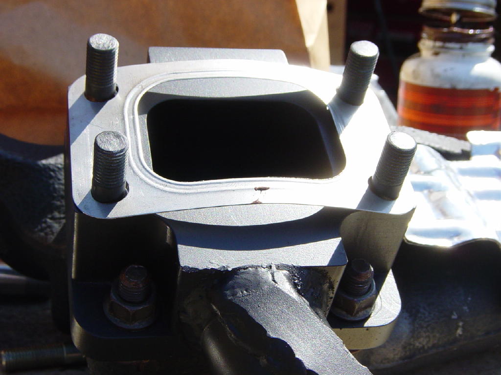
Install the turbo gasket onto the adapter. You can get it to stay by arching the gasket slightly by bending it over your forearm (unless you have tiny/bony forearms that would crease it :-)).
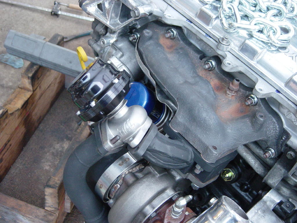
Step 28:
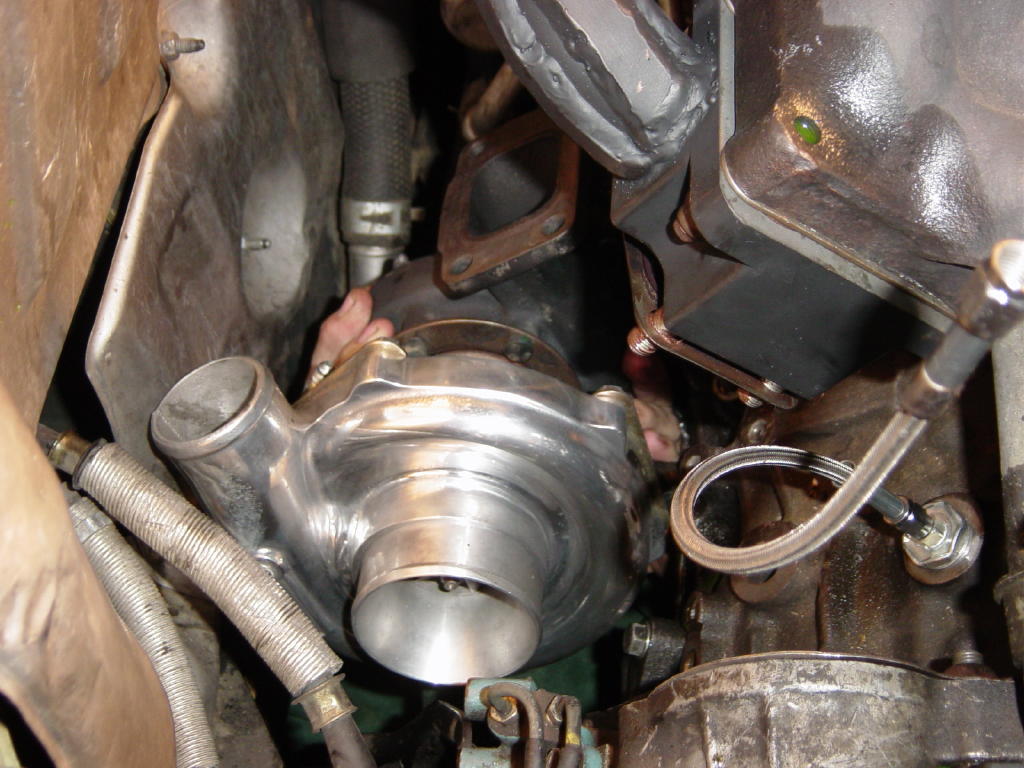
Now install the turbo. This is best done from the bottom to avoid scratching the polished housing. It will likely require some extra pressure applied to the firewall heatshields (or optionally, removal of the firewall heat shields) by the turbo (put a rag between the turbo and the heat shields to keep from scratching it) to get it to slip over the studs in the adapter. While holding the turbo in place, start a couple of the nuts to hold the turbo in place. Once it's on, put on the remaining nuts and torque them down to approximately 50 ftlbs. Install the oil feed line to the turbo.
Step 29:
Install the air fittings onto the wastegate. You will want to put one crush washer on each side of the banjo fitting before passing the screw through the fitting and screwing it down into the wastegate ports. There is a port on 'top' and one down on the 'side' of the wastegate. Leave the fittings a little loose as you will want to orient them once the wastegate is in the car. Install the wastegate gasket and wastegate onto the downpipe (with the downpipe out of the car is easiest) using the 2 hex head black 13mm (8mm shank) fasteners and lock washers provided in the turbo kit with some anti-seize on the threads (these bolts are gold colored in the pictures). Be sure to properly orient the wastegate with the exit of the wastegate going into the dump tube (note orientation in pictures). It is optional to install a jam nut on each of these bolts to keep them from backing out.
NOTE: The gaskets included with the wastegate are not standard Tial gaskets as the Tial gaskets will blow out in 3 weeks or less of regular driving, KO Racing has substitued higher quality fire-ring gaskets for these connections to provide leak free boosting. Should you ever have a need to replace these gaskets, they can be obtained from KO Racing for $8.50 each.
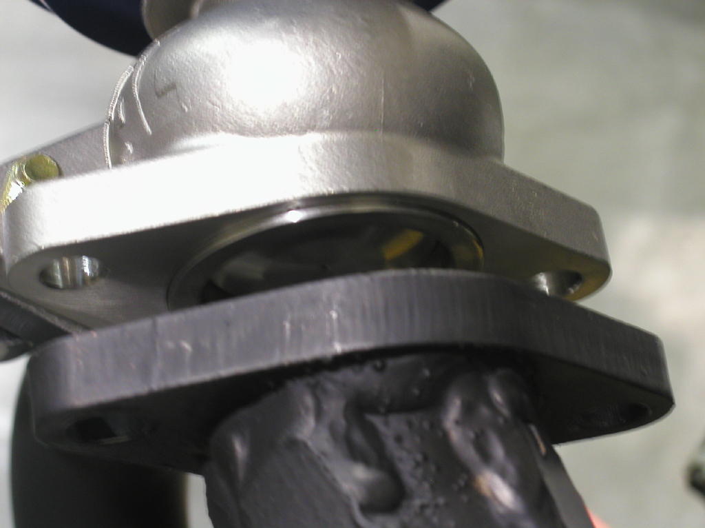
Step 30:
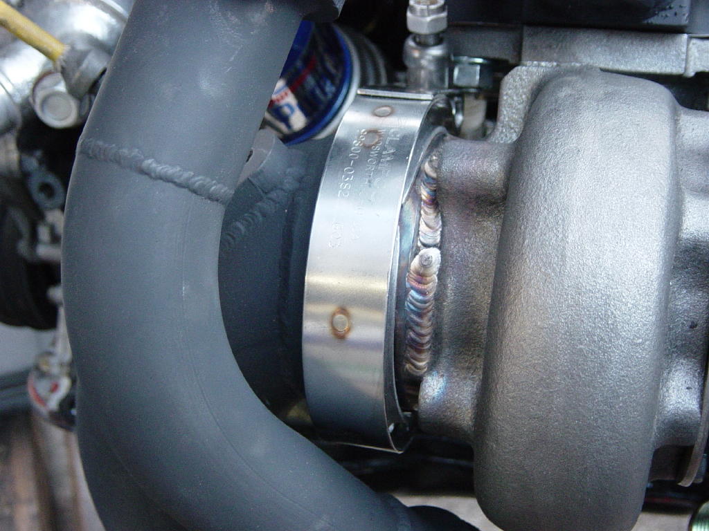
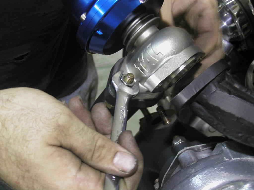
Remove the nut on the cross bolt of the provided v-band clamp (but don't lose it), and place the clamp onto the flange of the turbine housing. Orient the clamp as shown.
Step 31:
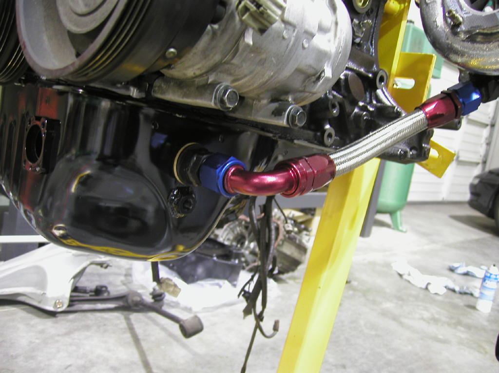
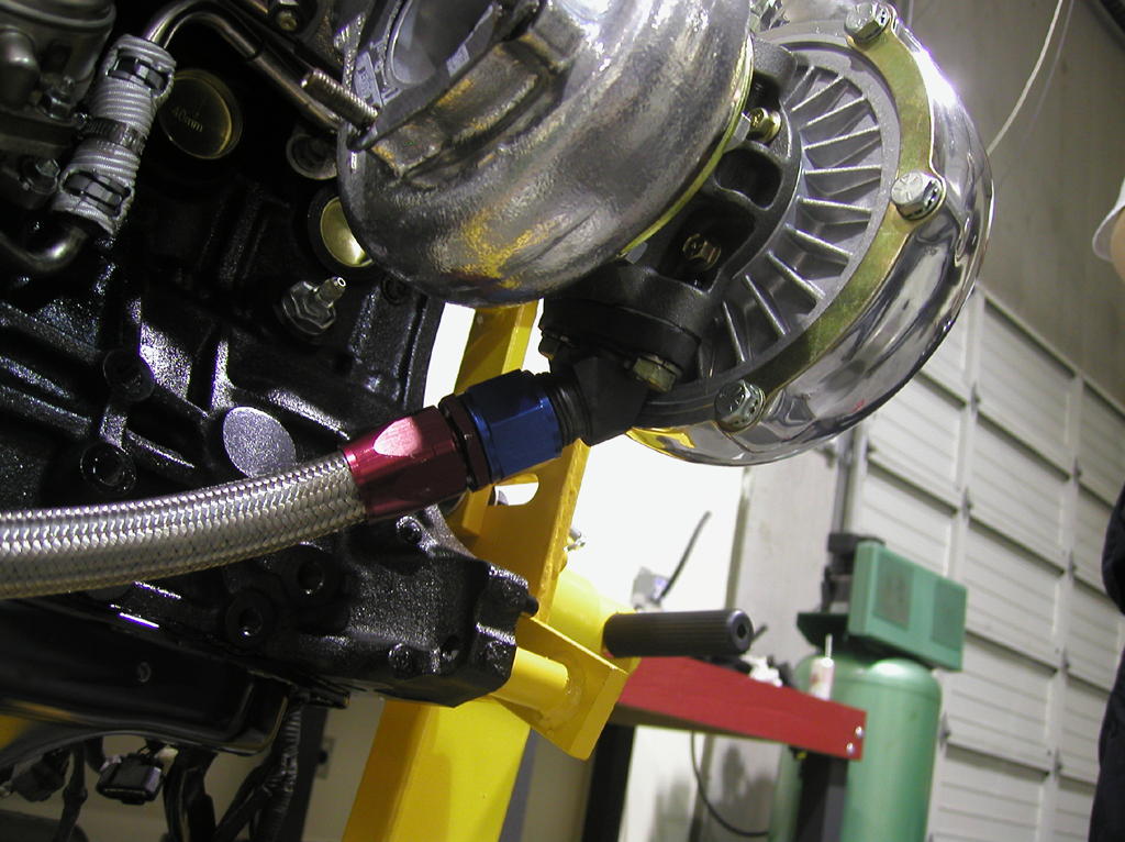
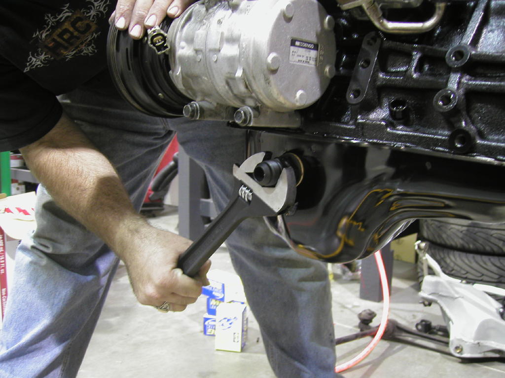
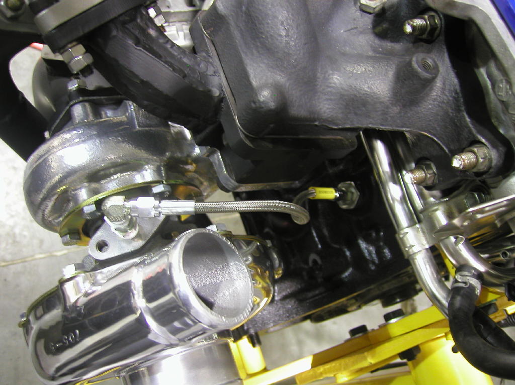
Install the -12 AN oil return line onto the fitting on the bottom of the turbo (the straight hose end goes at this end). Tighen this fitting down just a bit past snug, but do not overtighten. This fitting is at an odd angle, and it may be difficult to get a wrench on it straight -- this is ok as the fitting doesn't neet to be highly torqued to seal. Leave the oil pan (90 deg) end disconnect at this point as it will make downpipe installation easier.
Step 32:
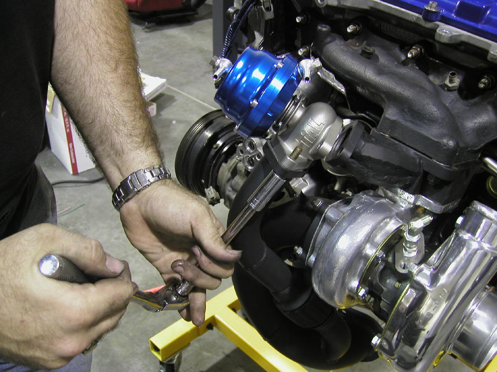
Install the downpipe onto the turbo. Place the v-band flange of the downpipe into the v-band clamp on the turbine housing. Orient the clamp as shown, and while pinching the clamp together (to get the cross-bolt to stick out of the clamp) reinstall the nut and tighten finger tight. The nut is a self-locking nut and will require a wrench to tighten down beyond the first few threads. With the clamp oriented as pictured (top just touching the turbine to adapter mating flange), it is possible to get a straight shot from the top of the engine bay at the cross bolt nut with a 1/2" (13mm) socket and 3-6" extension. Do not tighten this clamp to the point that the downpipe doesn't rotate agains the turbine housing at this point.
Step 33:
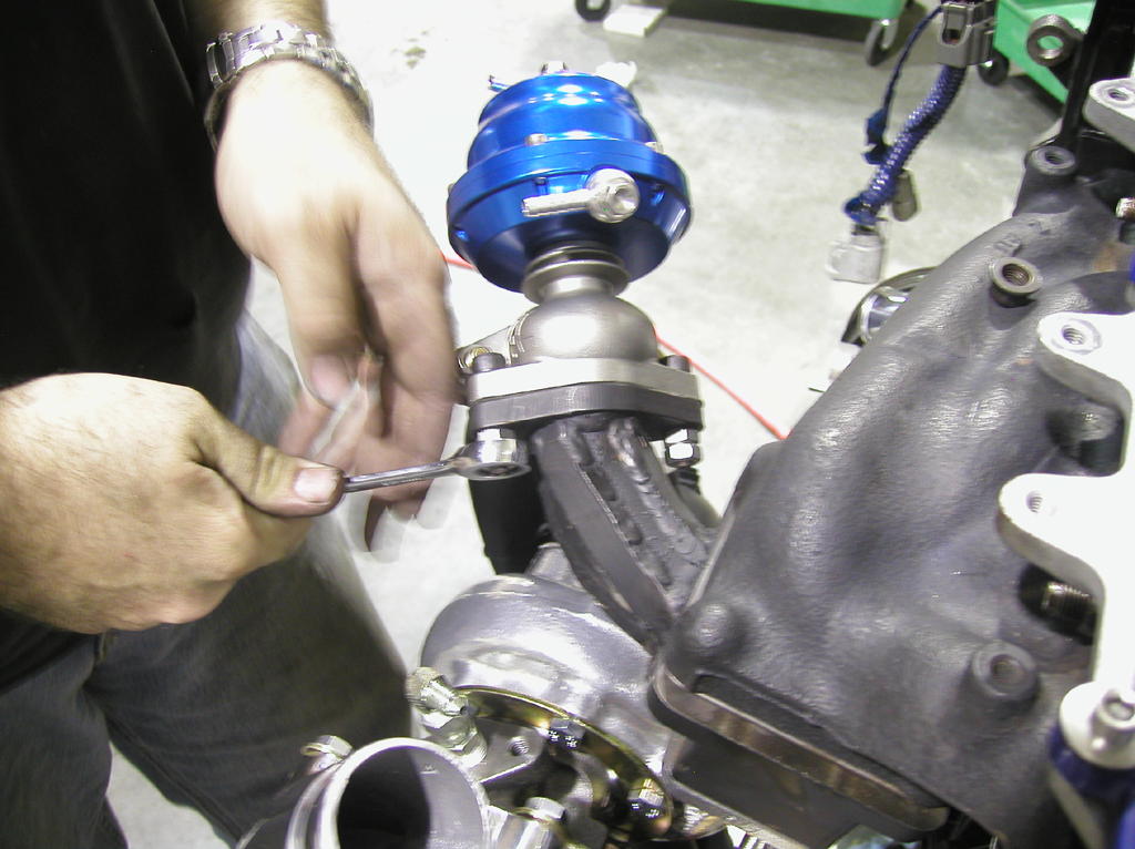
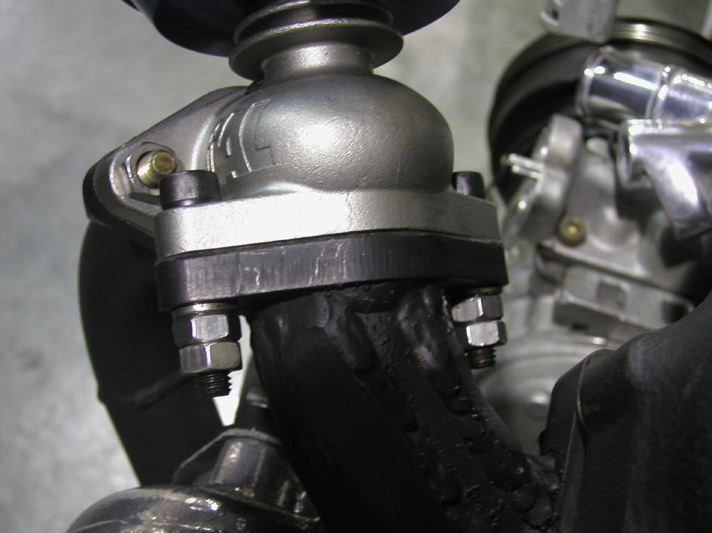
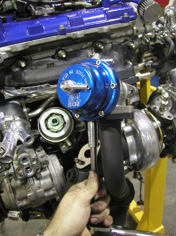
Install the valve seat included with the wastegate. It is a tight fit and one side is flat while the other side has a beveled edge on it -- the flat side goes out toward the bottom of the wastegate (it should be apparent which way this seat should go). DO NOT LEAVE THIS SEAT OUT OR YOU WILL NOT BE ABLE TO BOOST (at least not very well). Once you've located the seat, install the remaining wastegate gasket and wastegate onto the turbo adapter using the 6mm socket head (allen head) (8mm shank) black bolts included in the turbo kit. If the wastegate appears to be twisted a great amount or not lining up planar to the mount coming out of the turbo adapter loosen the hex head bolts used to install the wastegate onto the downpipe and re-orient the wastegate -- note that some misalignment can be taken up by the flex section in the dump tube. Use the 'top lock' locking nuts (thread deforming nuts) provided (and anti-seize) to bolt the wastegate to the turbo adapter.
Step 34:
Install the 90deg end of the oil retrun line onto the oil pan fitting. Tighen this fitting to just past snug. If the oil return line is closer than 1/2" to the downpipe, try to gain clearance by rotating the fitting coming out of the bottom of the turbo to anlge the return line away from the downpipe. If you loosened the engine oil cooler to remove the ct26 downpipe, retighten it now being very carful to not cross thread the large 30mm stud that goes through the center of it, and don't forget to put the 12mm bolt back into the side of it. Also reinstall the oil filter once the oil cooler is tight.
Step 35:
Install the 2 30mm long stainless studs into the Toyota style O2 sensor flange (with anti-seize) and reinstall the gasket and the o2 sensor with the 2 12mm flange nuts provided.
Step 36:
Install the downpipe support bracket (don't tighten it until the b-pipe is back on -- but be sure to start the bolt that retains it into the engine block). Reinstall the b-pipe onto the car. Once the b-pipe and support bracket are tight, tighten the v-band cross-bolt to 10ft-lbs.
Step 37:
Install the 3" ID silicon hose over the end of the stock rubber elbow. NOTE: This is probably the most difficult part of this installation. To make this step easier, be sure to use some type of lubricant to slip the silicon hose over the stock rubber hose. Once the silicon hose is covering the recessed clamp area of the elbow, use one of the large hose clamps provided with your kit to retain it over the stock elbow (though it may seem like nothing could remove it, you don't want to have to put this back on again). Loosely place a second large hose clamp around the other end of the 3" silicon hose and reinstall the air intake system onto the inlet of the turbo. Tighten the second large hose clamp once the silicon hose is fully seated all the way around the turbo compressor inlet.
Step 38:
Install the silicon reducer coupling and the provided constant torque hose clamps over the compressor outlet (the small side of the reducer goes on the turbo). NOTE: the reducer is sized to work with the stock turbo compressor out pipe or hot-pipe (aluminum pipe the BOV mounts on). If you have other than stock sized pipe in this area, you will need to obtain a different reducer coupling -- the turbo oulet is 2" diameter.
NOTE: The next step is to install the silicon vacuum lines that will connect the compressor outlet to the wastegate. Depending on your boost controll device, the exact installation may vary.
Step 39a: Wasegate boost control only (simplest installation)
Install a length of 6mm silicon hose (provided) to connect the turbo pressure source on the compressor housing to the lower of the ports on the side of the wastegate, leaving the 'top' port open to atmosphere. This will set your boost level at the spring pressure of the wastegate (10psi or .7bar standard). Use the small zip ties provided to clamp the ends of the silicon hose over the fittings.
Step 39b: Electronic boost control (be sure to set your boost controller to control an external wastegate if it has that capability)
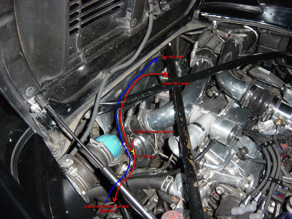
Install a length of 6mm silicon hose (provided) to a "T"-fitting (provided) just off the turbo pressure source on the compressor housing. Run one side of this "T" to the "IN" on your boost control solenoid, and the other to the lower port on the side of the wastegate. Run a 6mm silicon hose from the "OUT" on your boost control solenoid to the top port on the top of the wastegate. Use the small zip-ties provided to clamp the ends of the silicon hose over the fittings.
Step 40:
Install the compressor outlet pipe onto the car and tighen all the clamps retaining it. It may be necessary to clock the compressor housing in some cases to have better alignment to the turbo out pipe. This can be accomplished by loosening (not a lot) the 6 bolts holding the compressor housing to it's back plate, and lightly tapping the housing to rotate it up or down as required. Be sure to re-tighten these bolts if you do re-clock the housing. Hook up the boost source line to the BOV if you removed it. If you are re-routing your BOV to the intake side of the turbo (like stock), you may need to lengthen the return pipe or use some hose instead to hook up the BOV.
Step 41:
Top off the coolant and the oil if you lost any during the installation. Check all connections to make sure they are tight. Reinstall the strut tower brace.
Step 42:
Now ENJOY!
Final Notes:
- It is always a good idea to retighten all the bolts once the vehicle has been driven at operating temperature, then allowed to cool, but the critical ones are the 2 13mm wastegate retaining nuts. Be sure to re-tighten these a day or two after the install (or while the vehicle is still hot -- being careful to not burn yourself).
- Setting the boost level should be done by cautiously and in small steps while monitoring EGT's and Air/Fuel ratio. KO Racing does not recommend boosting beyond 16-17psi on an otherwise stock engine (and stock ECU) without proper tuning and measurement of the air/fuel rato. For more power, you will need increased fuel system capacity, and the ability to tune it with the help of a knowledgeable tuner and a dyno. Failure to heed these cautions releases KO Racing from all liability related to the use or installation of this turbo kit.
- Adhere to all state, federal, and local laws regarding speed and use of this equipment on the street.
- Thank you for purchasing a KO Racing Street Brawler Turbo Kit and I hope you enjoy it as much as I enjoyed making it for you.